Headgear Solar wearables
Introduction
The name of the project itself makes the user imagine of the product that there are some Head wearables which can be used to charge our Luminar Wearables. In our future the gadget with gesture are more preferable for interpreting the person’s activity. That can be true but the electronic gadgets required some power to work on continuously, so there is various source of energy to power our gadget but the most significant way is to use a secondary cell like Lithium ion which is very demanded in the market of batteries due to its higher capacity and long life. So our project is one of it in which we will convert the Solar energy to Electrical to Chemical energy.
Description
The Headgear wearable is device that can be used to charge our Luminar wearables, there are many options to choose our Luminar wearable chargers to kept on the Body attires of person. But our purpose to choose the Solar wearable as a headgear was for the that there would be no restriction of Solar Irradiance to charge our Batteries. For e.g. if there is any charger attached at a Lower or chest attires of Body then there is limitation of Solar irradiance to charge the Luminar batteries so the best location to get on a person’s body is the head it will see the sun for all the time with an angle and for peak charge the person can get benefit of Fast charging during the Mid of Afternoon when the angle of Sun is in nearly to perpendicular.
Now let’s discuss the wearable to be chosen. The best option to choose this kind of activity are a Hat, Helmet, spectacles and many more. But what we have plan to choose was a Hat that can be wear at any activity like Sports, going to some conference, etc. and it’s a bit obvious that can be use in indoor activity because of its work on the solar irradiance. Generally, there are variety of Solar panel available like Solar Fabric, silicon junction and many more. But the major cells are to used are for Silicon Solar cells which are chipper and now they are coming with the Waterproof grade and with some proper isolations of Plastic box it can be isolated fully with the human body. The Hat is the perfect location on which the person can get the solar irradiance without any disturbance.
Our circuit is basically a closed loop circuit in which the circuit doesn’t required any controller interference to trigger there are latch kept in the circuit for hysteresis to reduce the impact of high frequency noise so that the electronics switch not get any stress issue. There are the Limits set in the Voltage divider to trigger the charge and discharge as per user specific define values. For the following circuit let’s say I want to operate on a range of Battery from 3 V to 3.7V then the divider resistor is set at R1 = 7K Ohm, R2 at 420 Ohm and R3 at 1.7K Ohm. The formulas are given ahead in the report to tune the value as per user define. By that divider we have Latch transistor which are triggering and making On/OFF the Main Line PMOS to trigger as a switch.
Part List.
- Solar cells.
- Hat.
- Electronics PCB.
- Li-ion Battery 3.7V.
Material Lists.
The list of Materials is:
- Solar cells 6V 100mA with Dimension of 70X70 mm.
- Stainless steel conductive thread.
- Bare PCB for Electronics Circuit.
- Resistors with Tolerance of 1% and 0603 Package.
- 7K Ohm resistor – 2No’s.
- 1.1K Ohm resistor – 4No’s.
- 10K Ohm resistor – 2No’s.
- 420Ohm Resistor – 1No’s
- 1.7K Ohm Resistor – 1No’s.
- Capacitors Ceramic MLCC with 0603 Package X7R or X5R or Ceramic
- 0.1uF Capacitor 2 No’s.
- Transistor BC847 – 4No’s SOT23-3 Package.
- Diode BAT854SW-QX Schottky Diode with 450mV Vf.
- PMOS – FDN358P 1 No’s with Vgs 4.5V and RDS(on) 0.2Ohm 1No’s.
- Li-ion Battery 3.7V with 800mAh.
- Plastic Box Design D 52mm x 32mm.
Circuit Diagram:

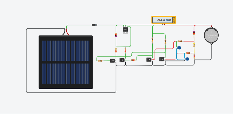
In the Image the cells available in Tinker cad was a button cells but the actual cells are different.
In our project the technicality is that this circuit don’t required any external reference or Pulls, it is having an internal resistor base triggering circuit for triggering the circuit in between +3V of Vbat Min and +3.7 V of +Vbat max.