- By Tyler Jorge

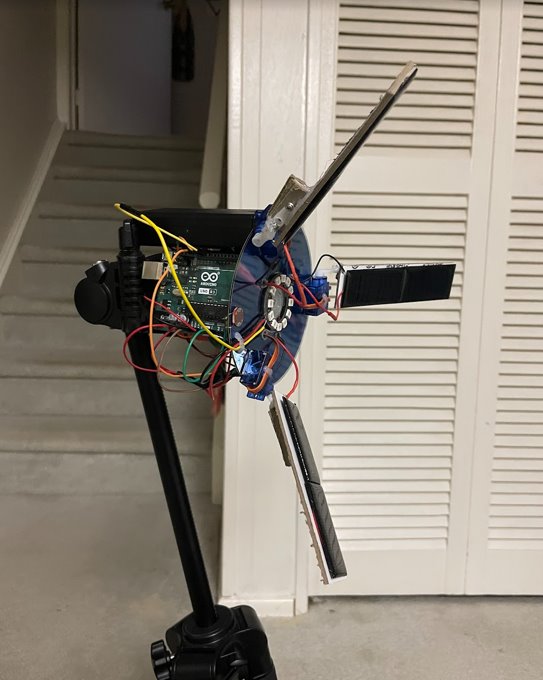
This project incorporates 6 solar panels (5v, 30mA) wired in parallel (5v, 180mA), hooked up to charge a single 18650 Lithium-Ion battery (3.7v, 3500maH), which is then used to power an Arduino Uno. Additionally, there are 4 servo motors (3x 180°, 1x 360°) that are used to move the solar arms, and rotate the CD that the entire device is mounted on. There is also a LDR (light dependent resistor) mounted on the face of the CD to measure environmental light levels and feed that information to the Arduino.
The way this device works:
- The solar panels charge the battery when exposed to sufficient light levels.
- The battery is hooked up to a voltage booster to increase the voltage from 3.7v to 5v (enough to power the Arduino, servo motors, LDR, NeoPixel ring)
- When the LDR detects low light, the arms are locked in a 90° position and the disc is unmoved
- When the LDR detects high light, the arms flap between 15° and 85°, and the disc rotates by 180°
- When the LDR detects light above a certain threshold limit, the arms remain closed at a 15° angle to concentrate the solar panels on the light source
- The NeoPixel ring located at the centre of the disc is supposed to blink when high light is detected, unfortunately this part of the code was difficult to implement
Concept / Inspiration

I took inspiration from the popular video game “Death Stranding” by Kojima Studios. In the game, the main character has a shoulder mounted device (called an Odradek) that acts as a terrain/enemy scanner. The device works by blinking its lights and flapping its arms to notify the player of various points of interest.


The Solar Circuit
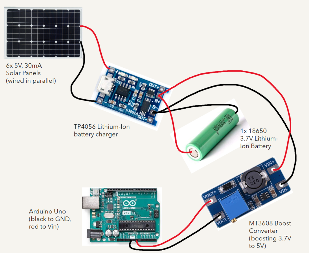
The solar panels on my wearable are wired in parallel to provide the current required to power all the various features of the device. Since the solar panels output 5V already, there was no need to wire them in series, instead, wiring them in parallel provides sufficient amperage for the servos, LEDs, and LDR.
The panels are hooked up to a lithium-ion battery charge module (TP4056), which is connected to the battery as well as a voltage boost converter (MT3608) which boosts the voltage output of the battery from 3.7V to 5V. This module is then hooked up to the Arduino which is used to connect all the servos and other features.
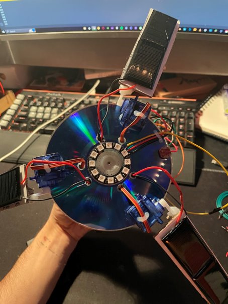
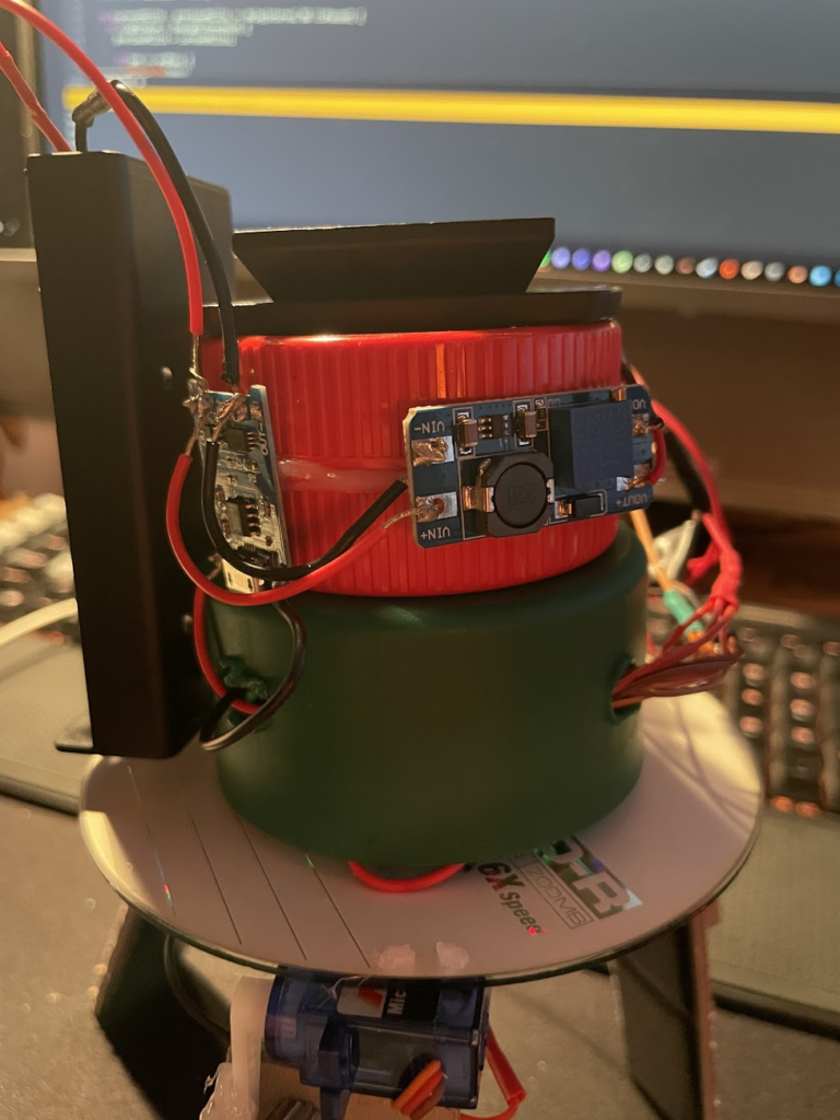
Project Images / Videos

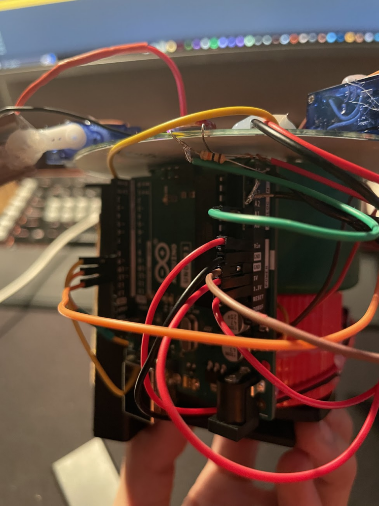
Link to a Youtube video demonstration:
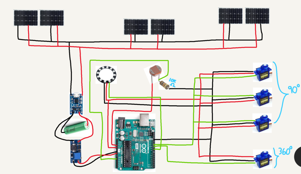
Circuit Diagram
Code
https://gist.github.com/tizza555/c0bb1f378216c2cfb9d62a3b0adb3f68
^ Link to GitHub gist with code used